A Hermetically-Sealed LC Resonator for Remote Pressure Monitoring
This work is fabricating an integrated LC resonator structure fabricated by using bulk micromachining and anodic bonding technologies. In this resonator structure, pressure change is monitored by a capacitive pressure sensor and results in the change of resonance frequency. The resonance frequency shift is detected by inductive coupling from an external transmission coil; therefore, pressure can be wirelessly monitored from passive LC resonators. It has been reported that intraocular pressure can be measured by passive LC resonator structure [1,2]. However, the previous structures are bulky and manually assembled in hybrid package. This is the first report on a fully-integrated LC resonator sensor which is hermetically sealed in a micromachined structure.
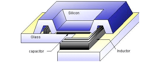
Figure 1
Figure 1 shows the structure of the proposed LC resonance pressure sensor. A capacitive pressure sensor is formed using p+ silicon membrane and a metal electrode on the glass substrate. An inductor is defiend outside the pressure sensor diaphragm and is connected to the capacitor electrodes. This inductor is surrounded by thick p+ silicon rims, so that the whole structure is hermetically-sealed. Only the silicon and the glass substrate are exposed externally, allowing this structure to be used safely for biomedical applications.
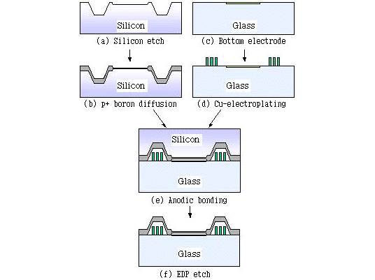
Figure 2
Figure 2 briefly shows the fabrication process of the structure. First, silicon is anisotropically etched in KOH to form a shallow trench (3mm) for the capacitive sensor diaphragm and a deep pocket where the inductor coil will be surrounded. Next, deep boron diffusion (12mm) is carried for the rim of the pressure sensor and the surrounding protection layer for the inductor. A shallow boron diffusion (3mm) is performed to define the pressure sensor diaphragm which is 1mm x 1mm in its size. On the glass (Corning #7740), metal electrode is deposited using Cr/Au (30nm/200nm) for the bottom electrode of the capacitive pressure sensor, followed by the definition of 30m m-thick, 15m m-wide inductor coils. Copper is electroplated to form the inductor coil with a thick photoresist pattern as a mold. It is important to reduce the resistance of the inductor in order to achieve a high Q at the resonance frequency. To complete the structure, the silicon wafer and the glass substrate are anodically bonded. During the ano dic bonding, the pressure sensor diaphragm as well as the inductor coil is hermetically sealed. At the same time one end of the inductor coil is electrically connected to the p+ silicon which is the counter electrode of the capacitive pressure sensor. Finally, bulk silicon is selectively etched in EDP, leaving p+ silicon layers to form the diaphragm for the pressure sensor and the protection rims for the inductor coil. Figure 3 shows the picture of the fabricated device taken from the glass side. The device size measures 2.8mm x 2.8mm x 0.6mm.
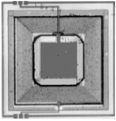
Figure 3
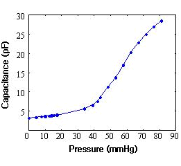
Figure 4
Figure 4 shows the measured characteristics of pressure sensor. Pressure sensitivity of 20000ppm/mmHg has been measured for the diaphragm thickness of 3m m. Total inductance of the coil has been measured as 220nH and its self-resonant frequency is about 500MHz which is much higher than the operating resonance frequency range of the LC structure (60-200MHz). Figure 5 shows the schematic diagram of the measurement system to remotely monitor pressure changes. Transmission coil transmits sinusoidal waveforms to the LC resonance pressure sensor at different frequencies depending on VCO signal levels. Resonance frequency can be detected from the impedance change at the node of transmission coil due to inductive coupling. Figure 6 shows the typical response curve observed at the detector circuit. From this resonance frequency, pressure responsivity has been estimated as 2MHz/mmHg. This micromachined, hermetically-sealed structure is suitable for biomedical applications such as intraocular, cadiovascular, and brain pressure monitoring.
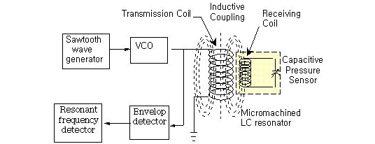
Figure 5
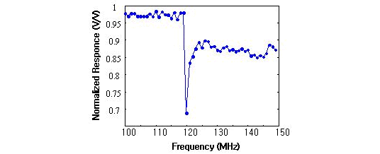
Figure 6

 Figure 1
 Figure 2
 Figure 3
 Figure 4
 Figure 5
 Figure 6


