
About
Fully integrated VCOs have been designed, fabricated and measured using MEMS inductor. A MEMS inductor with thick metal line and suspended structure has been proposed for high Q resonator and has been realized. Q of the inductors is more than 20 at different oscillation frequency. Integrated VCOs embedding the MEMS inductor have been implemented and very low phase noise could be obtained due to high Q inductor.
The concept of integrated VCO is shown in Fig. 1. Fully integrated transceivers are required as wireless devices become smaller. But there are some components that are difficult to be integrated. Voltage-controlled oscillator (VCO) is one of these components due to its high phase noise level. The major reason of high phase noise was that it was hard to obtain high Q resonator in integrated VCO. High Q inductor can be obtained by using thick electroplated metal and suspended structure. The suspended inductor effects on beneath circuit much less than CMOS inductor, which can save chip area.
Conventional circuit scheme has been used as shown in Fig. 2. CMOS cross-coupled scheme is known to have large signal swing and symmetric waveform. Oscillation frequency is determined by inductance and capacitance of LC tank. Active devices M1~M4 compensate the loss of LC tank. Buffer stage M5~M8 isolate LC tank from 50W terminated spectrum analyzer.
VCO core chip has been integrated with MEMS inductor. The MEMS integrated VCOs are shown in Fig. 3. MEMS inductors have been realized on top of fabricated CMOS VCO core chip. The inductors were levitated from substrate by 40 mm, Q of these inductor was measured as more than 20 at 1 GHz and 2.6 GHz, respectively.
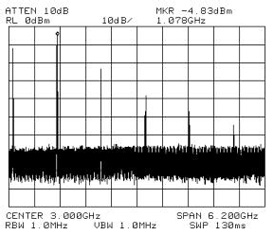
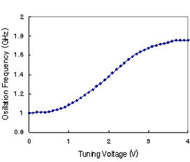
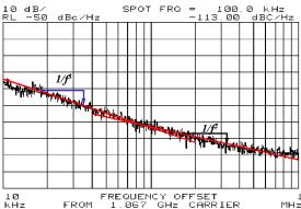
The measured results of 1 GHz VCO are shown in Fig. 4. 5 mA of current was consumed from 3 V power supply in VCO core. The VCO tuning was measured by varying control voltage of varactor from 0 to 3 V. Oscillation frequency was tuned from 1 GHz to 1.7 GHz. Phase noise has been measured as -113 dBc/Hz at 100kHz offset.
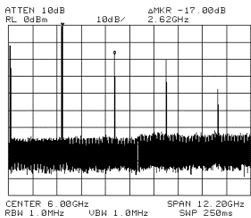
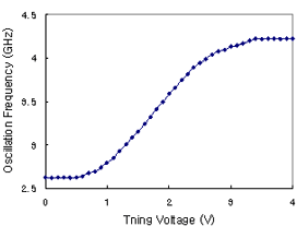
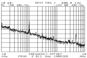
The measured results of 2.6 GHz VCO are shown in Fig. 5. 5 mA of current was consumed from 3 V power supply in VCO core. The VCO tuning was measured by varying control voltage of varactor from 0 to 3 V. Oscillation frequency was tuned from 2.62 GHz to 4.22 GHz. Tuning range was 1.6 GHz or 61%. Phase noise has been measured as -122 dBc/Hz at 600kHz offset.
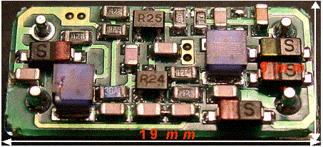
(1a) Phase I: Hybrid VCO (19mm x 9mm)

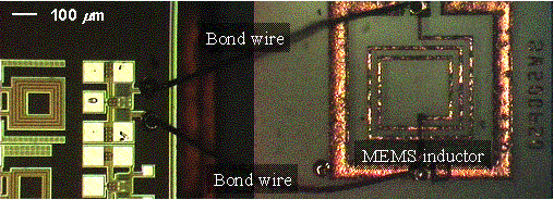
(1b) Phase II: Semi-integrated VCO

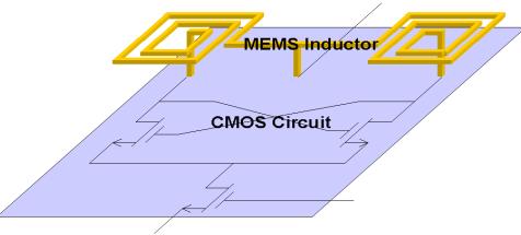
(1c) Phase III: Fully-integrated VCO
Figure 1. The Concept of Integration

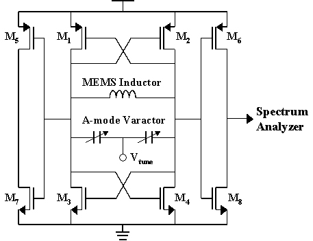
Figure 2: Circuit schematic

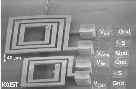
Figure 3: Fabricated VCO

 (a)
(a)
 (b)
(b)
(c)
Figure 4: 1 GHz fully-integrated VCO; (a) Output spectrum, (b) Tuning, (c) Phase noise

 (a)
(a)
 (b)
(b)
(c)
Figure 5: 2.6 GHz fully-integrated VCO; (a) Output spectrum, (b) Tuning, (c) Phase noise
Related Publications
- E.-C. Park, J.-B. Yoon, S. Hong, and E. Yoon, "A 2.6GHz Low Phase-Noise VCO Monolithically Integrated with High-Q MEMS Inductors," in Proc. ESSCIRC, 2002, pp. 143-146.
- Eun-Chul Park, Sang-Hyun Baek, Taek-Sang Song, Jun-Bo Yoon, and Euisik Yoon, "Performance Comparison of 5GHz VCOs Integrated by CMOS Compatible High Q MEMS Inductors," IEEE International Microwave Symposium, 2003, Philadelphia, USA.
- Eun-Chul Park, Yun-Seok Choi, Jun-Bo Yoon, Songcheol Hong and Euisik Yoon, "Fully integrated low phase-noise VCOs with on-chip MEMS inductors," IEEE Transactions on Microwave Theory and Techniques, Vol. 51, No. 1, pp. 289-296, Jan., 2003.


